I enjoy objects that bring modern technologies and natural materials together in a single object, especially if the finished product is romantic without being precious.
My most recently completed project involves old Soviet display technology, 3D printing, handmade (and hand-finished) hardwoods, and a lot of detail work. The finished work has come a long way from a handful of new old stock from the USSR, some plastic and metal bits, and a few sheets of wood. The full build took many hours and involved a fair bit of prototyping. The finished product has a modern look and finish, with the romanticism of pre-digital interfaces.
The beginning of the build involved a fairly complex board to run the nixie tubes. Nixies are power-hungry and high voltage (as much as 300v), so pulsed power is preferred to create the illusion of a fully powered tube. Think of it like an old television: by powering each bulb in succession fast enough, the display looks fully lit while requiring less power (and enabling longer life).
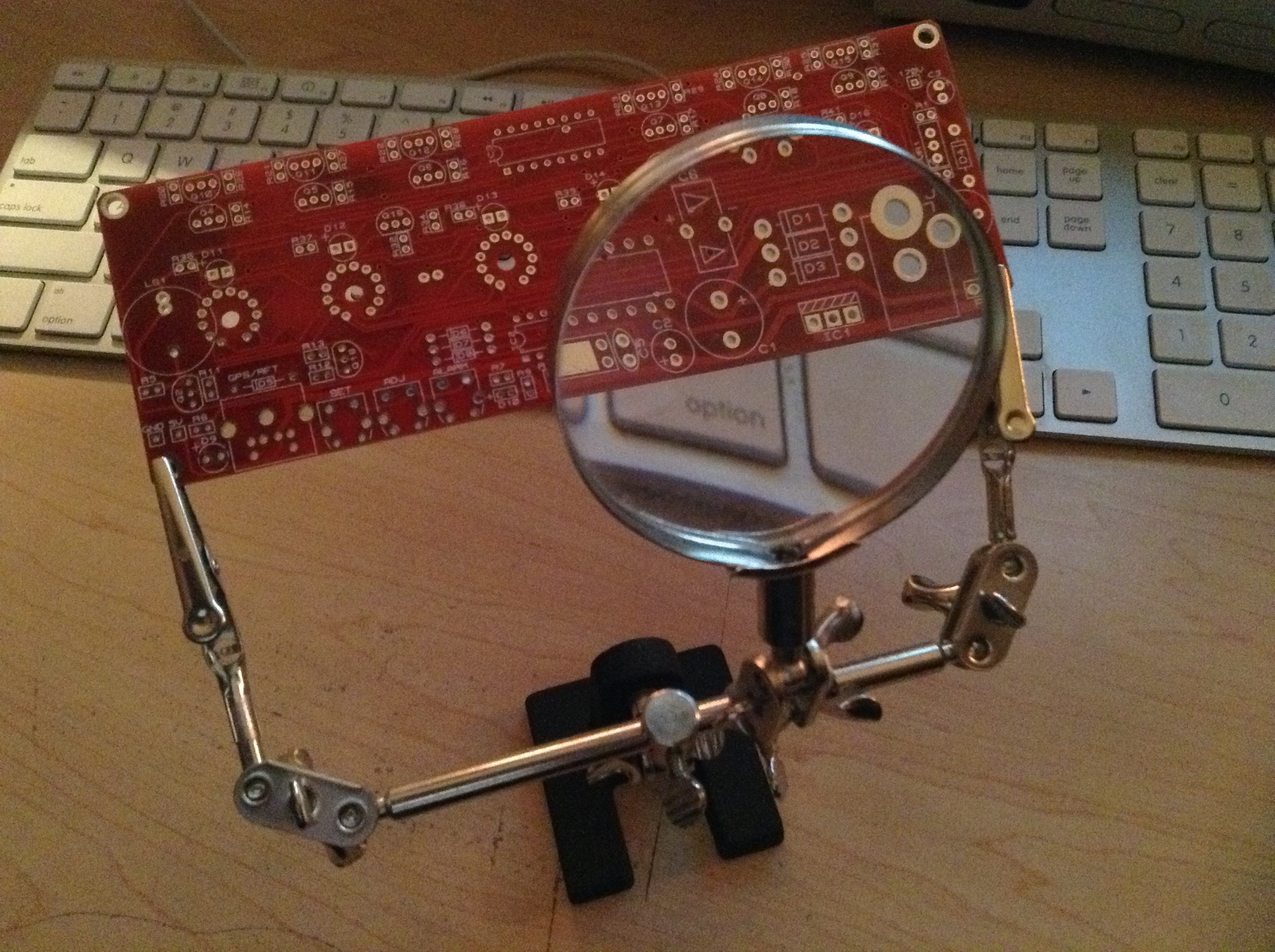
I build most of my projects out with power first; it reduces the risk of destroying components due to shoddy soldering or incorrectly assembled parts. Thus, my first step was to assemble the voltage step up and regulation on the board (and test it).
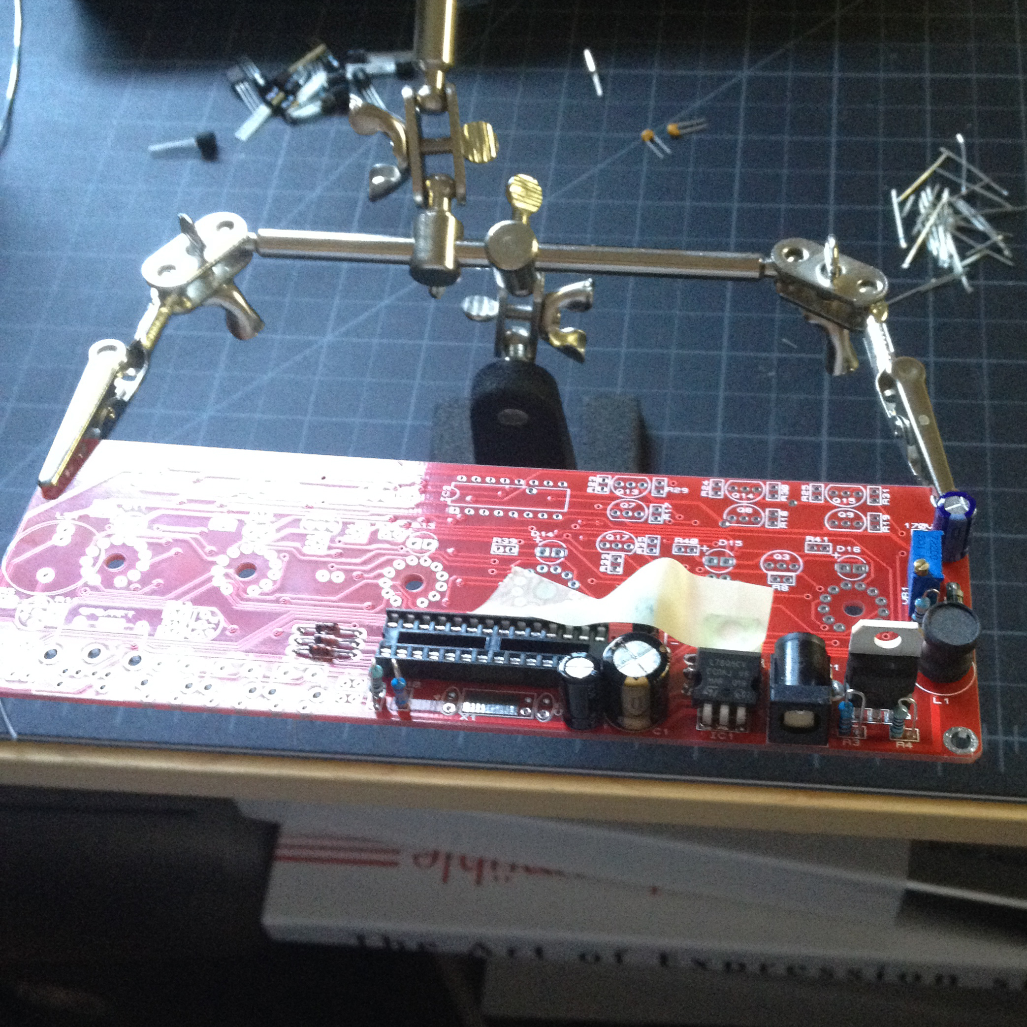
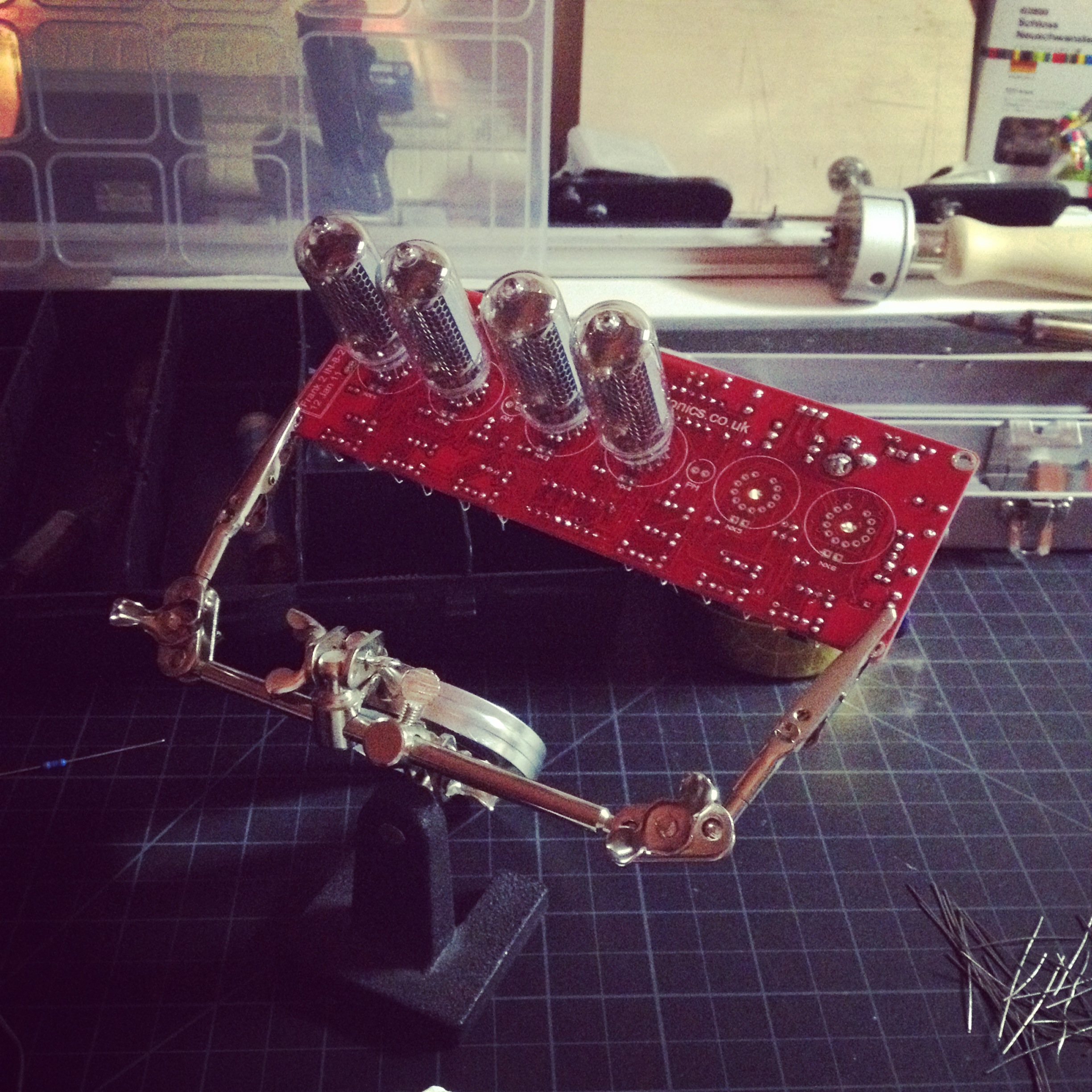
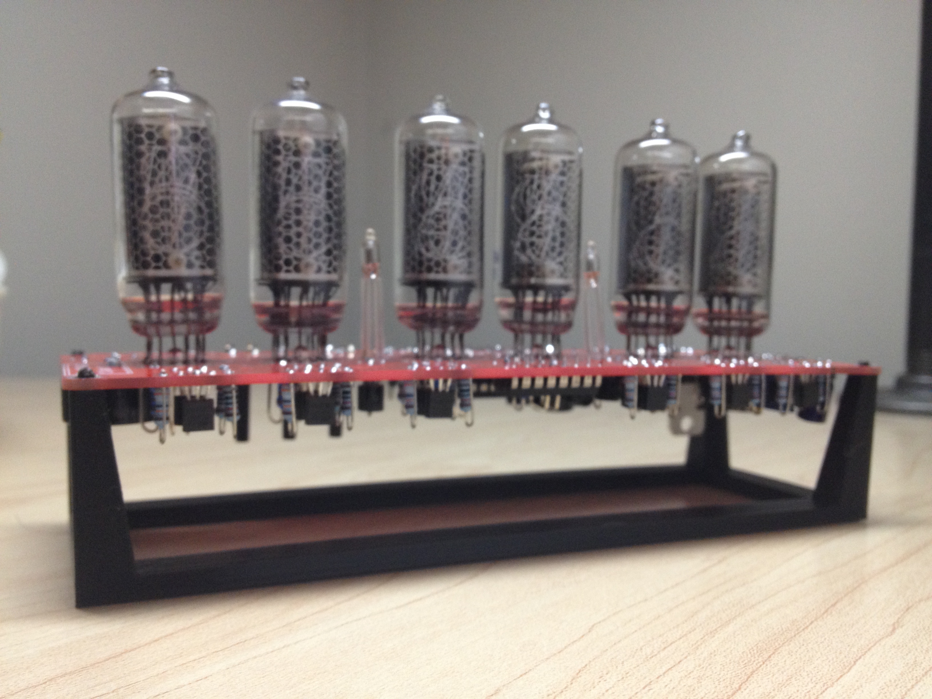
Once the components have been assembled into the board, soldered, and trimmed, the nixie tubes can be added. Nixies have a tremendous number of long leads (the wires that run from the filaments to the power supply) and soldering just one can take a while. Doing six takes quite a bit of time and requires some jig work to keep them parallel to each other, while keeping them equidistant from the board surface. They could be flush mounted (directly seated on the board) but I wanted the extra height for the finished illumination.
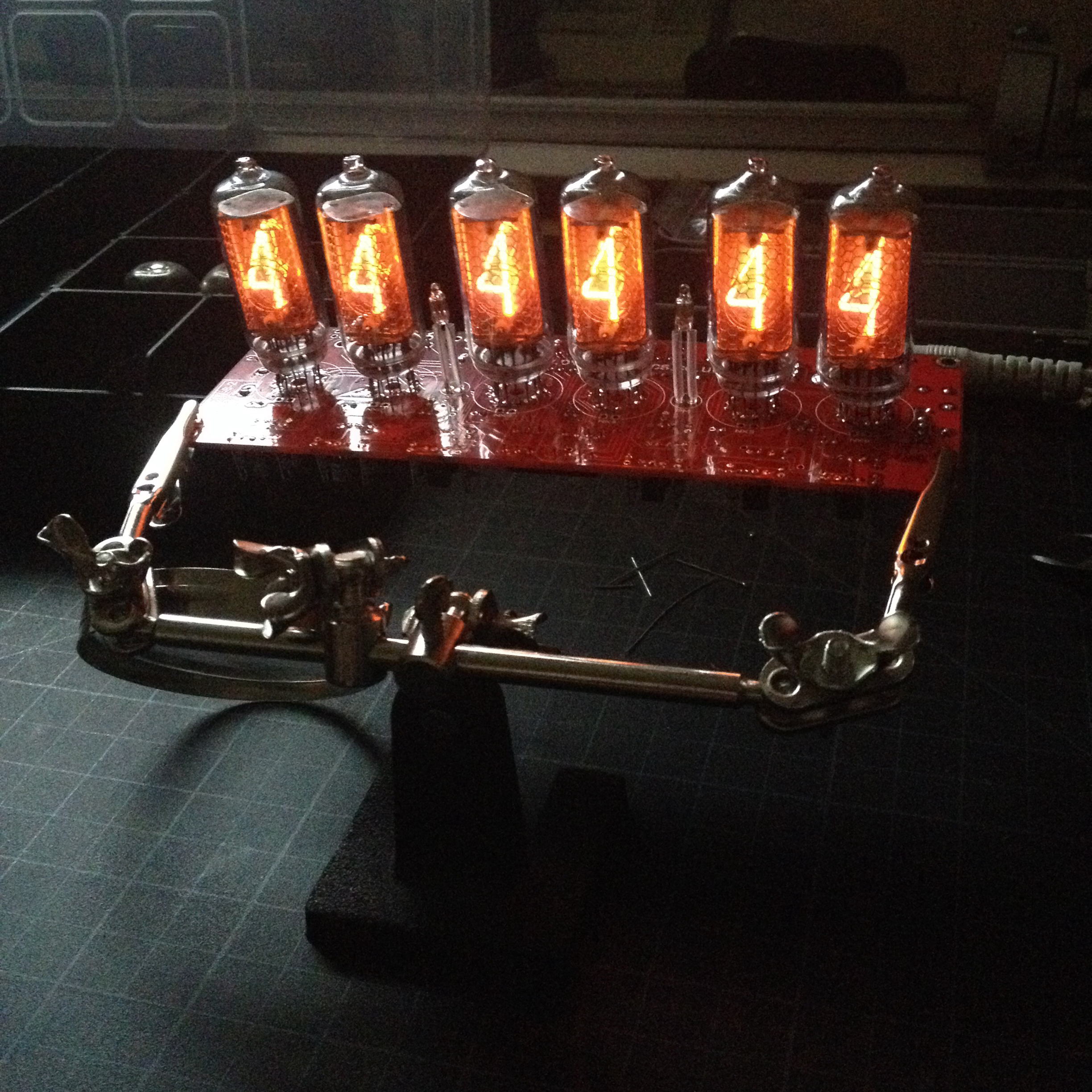
Once the voltage tests are complete, I test the major loops for the proper electrical behavior, then power the board and do a full test. The results are already very visually stimulating!
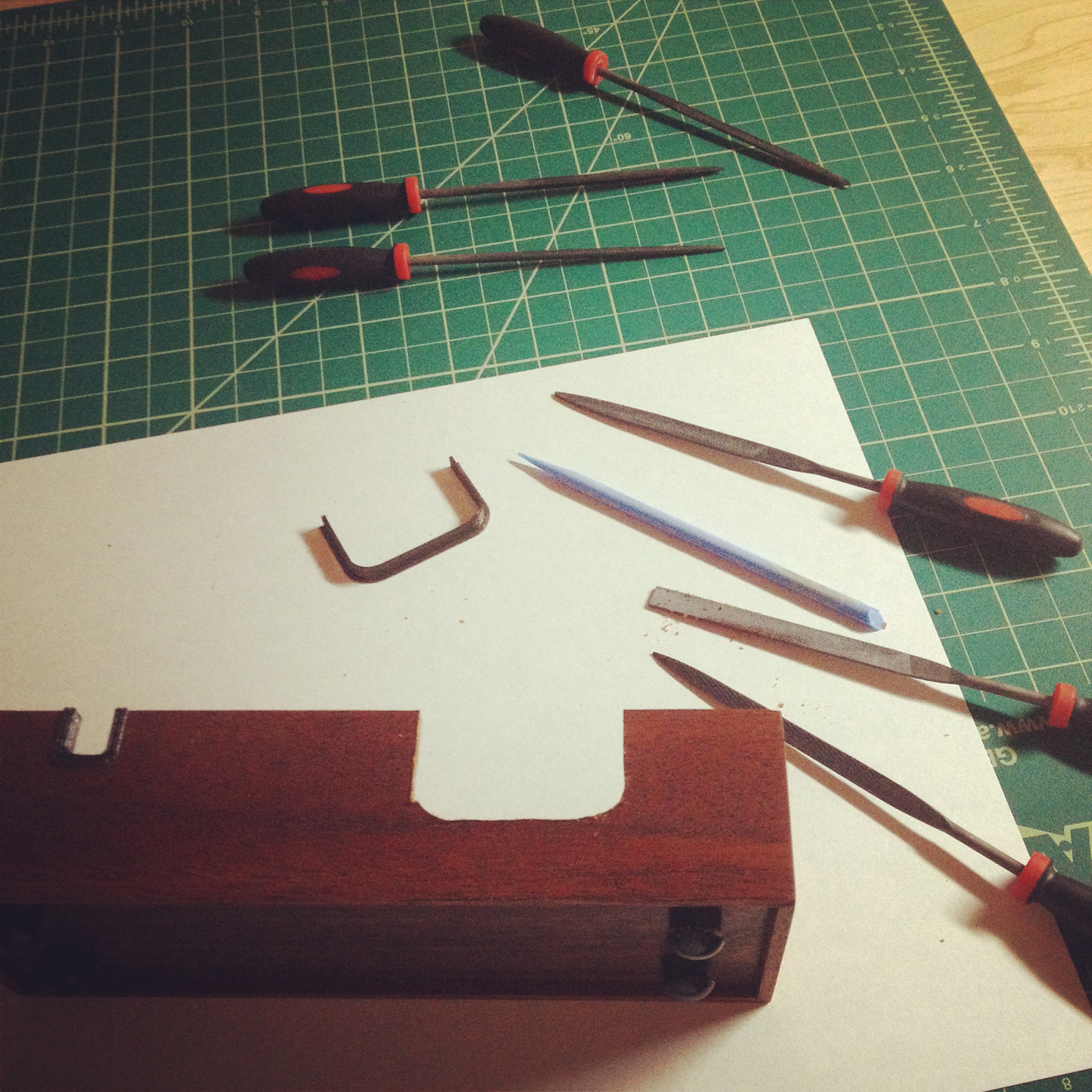
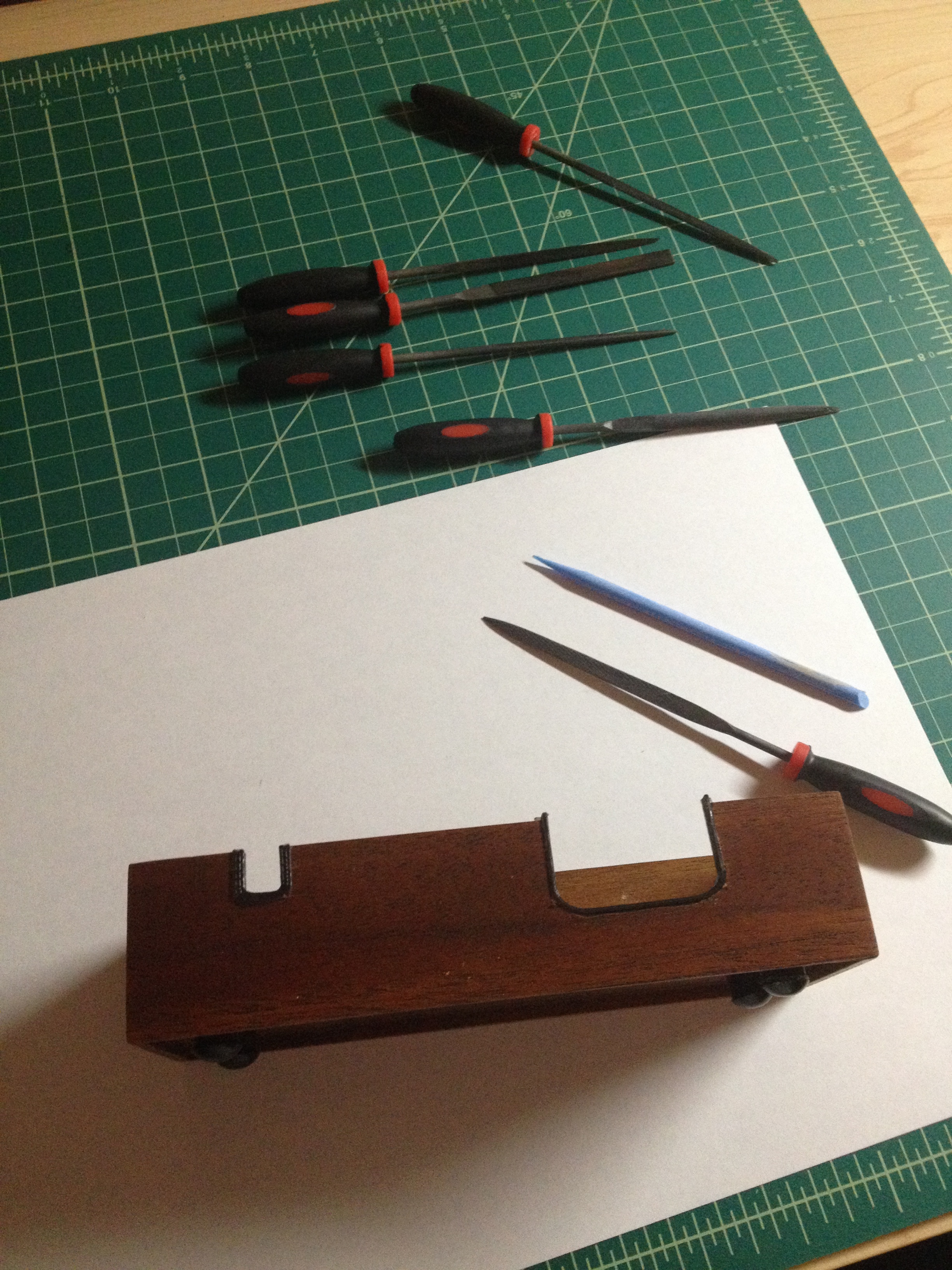
The technical work is essentially complete at this point. I moved on to constructing the case. I wanted the appearance of a block of hardwood mahogany but with a small footprint. I used some thin sheets, sawed them, and mated them appropriately. I cut the joints at 45 degree angles, forgoing complex joinery. The weight of the clock is not enough to stress the joints and my plan for the base will alleviate any stress at all.
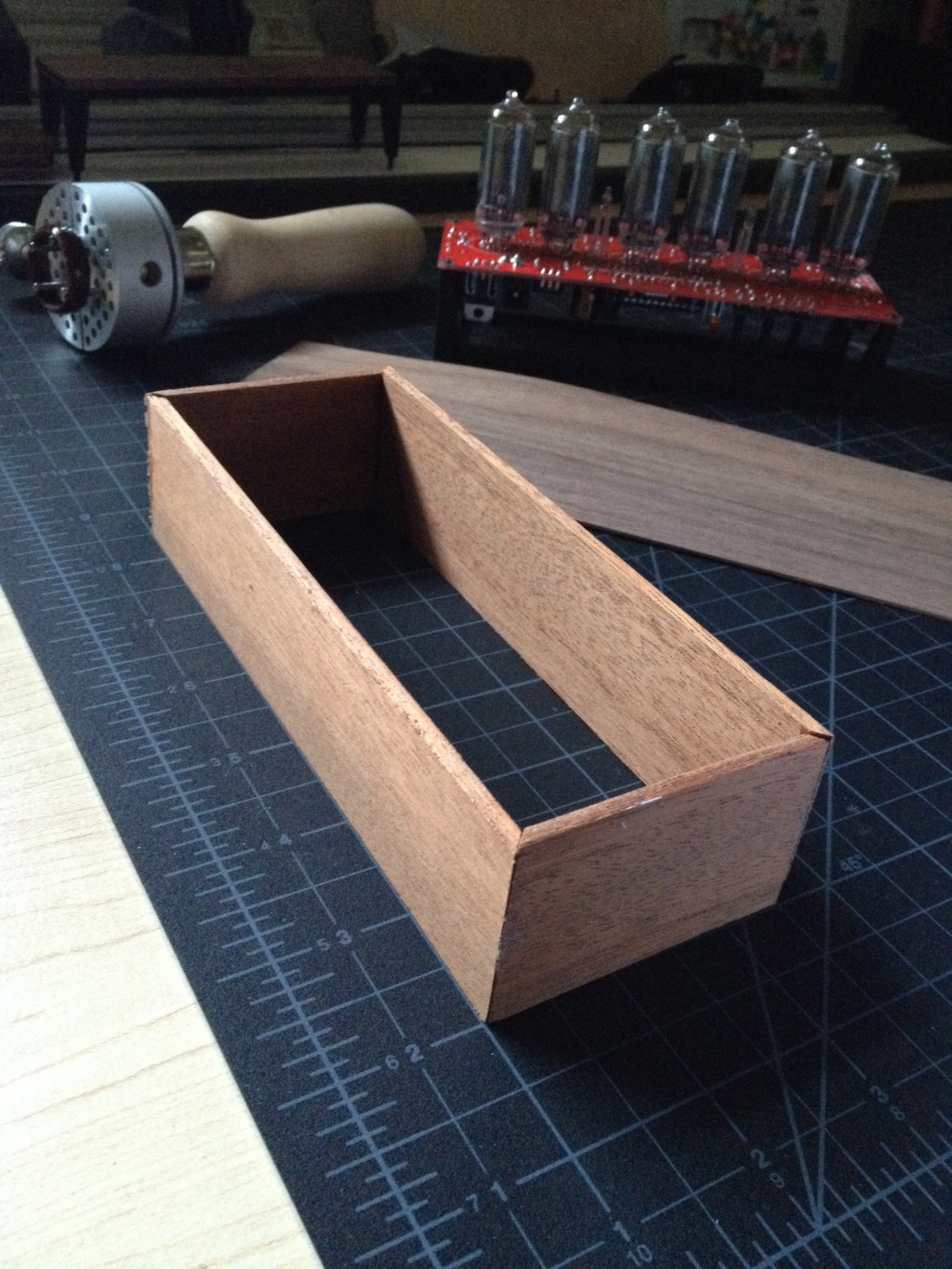
Next, I applied a veneer of walnut to a sheet of basswood by alternating the grain pattern. This will keep it straight, give strength without weight, and enable me to get away with another simple glued joint. Again, the final hardware will take most of the stress and send it directly into the board itself.
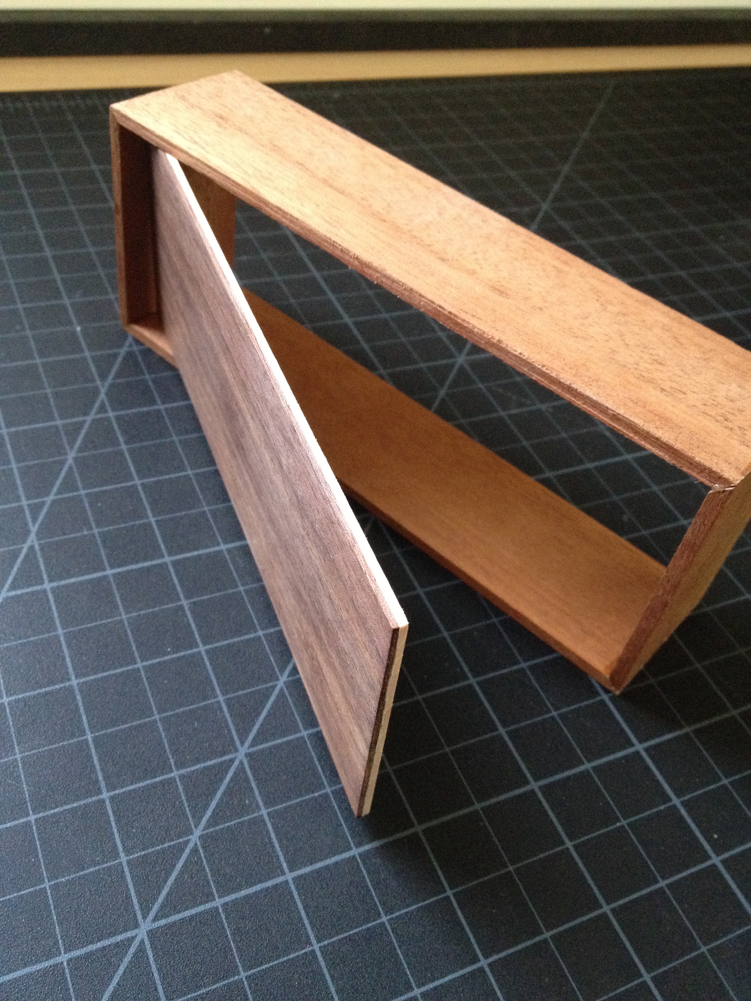
Next, I glued up the whole case. I’ll use some custom designed feet to raise the casework off the ground. This will provide a floating appearance and ensure airflow (just in case).
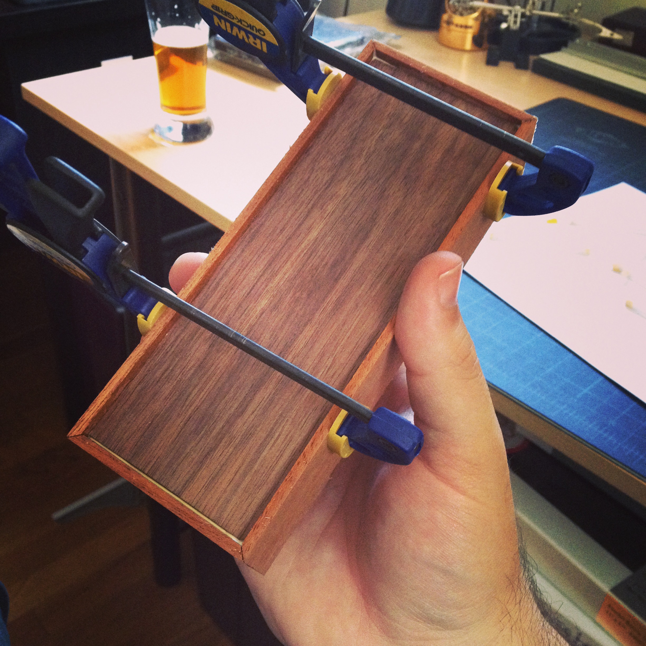
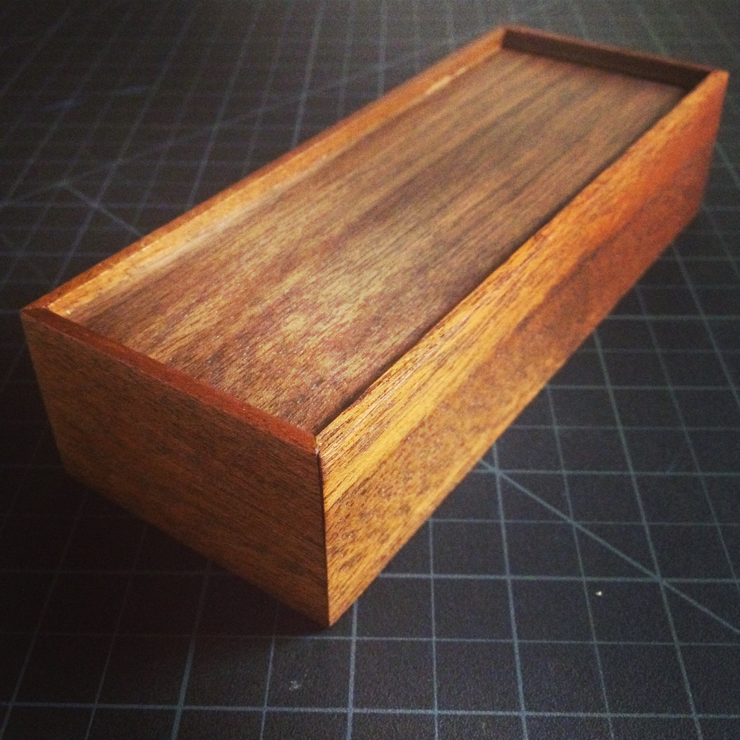
After 24 hours of time to really guarantee good curing, I removed the clamps and did four rounds of sanding. I attempted to preserve the sharp joints as well.
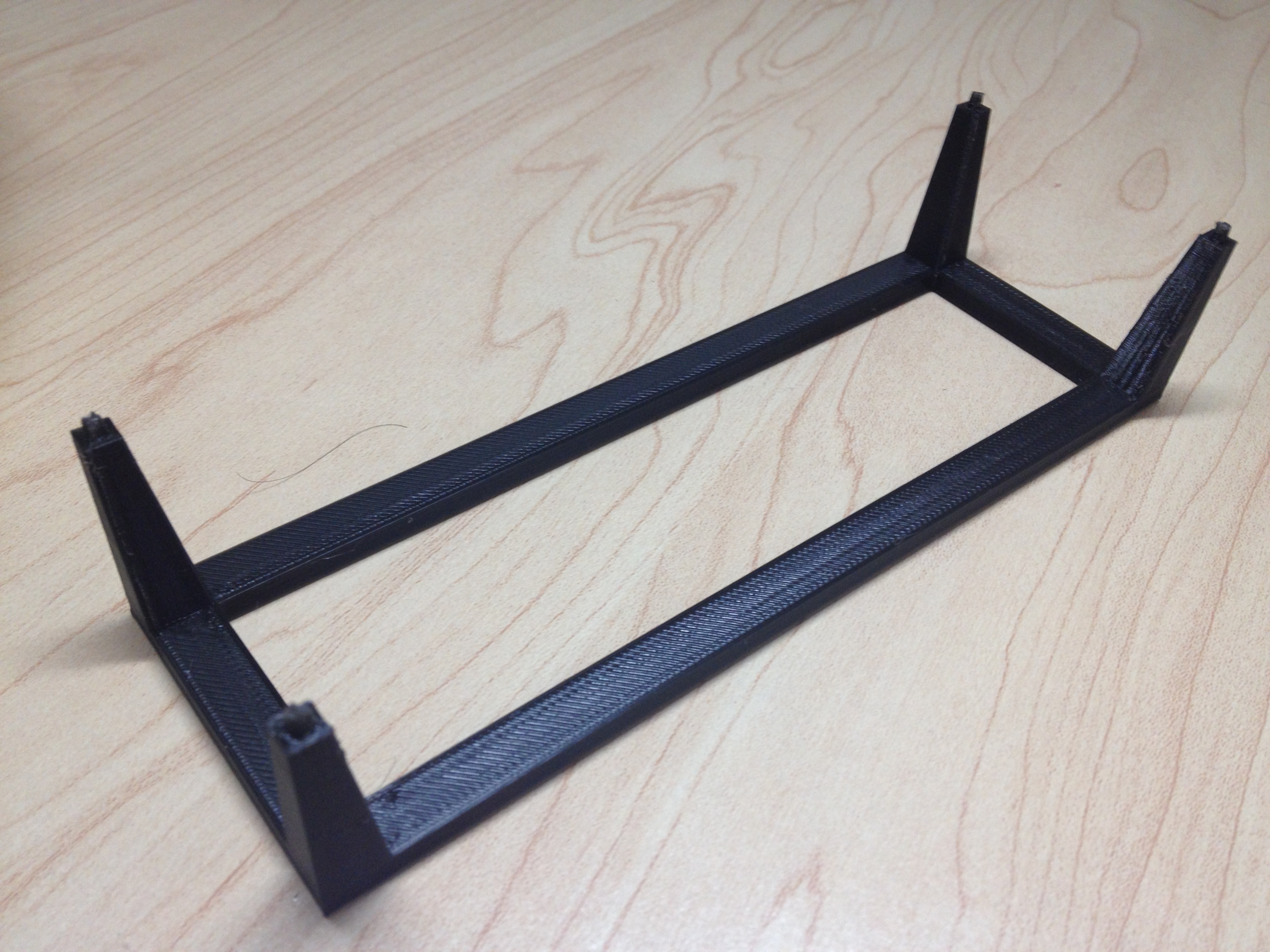
Next, I designed an armature to hold the board and tubes above the case by 1.5mm. The air gap will eventually be closed by the cover itself. This is 3D printed in PLA plastic using fused filament deposition technology (via a Solidoodle 3 and my own custom modifications).
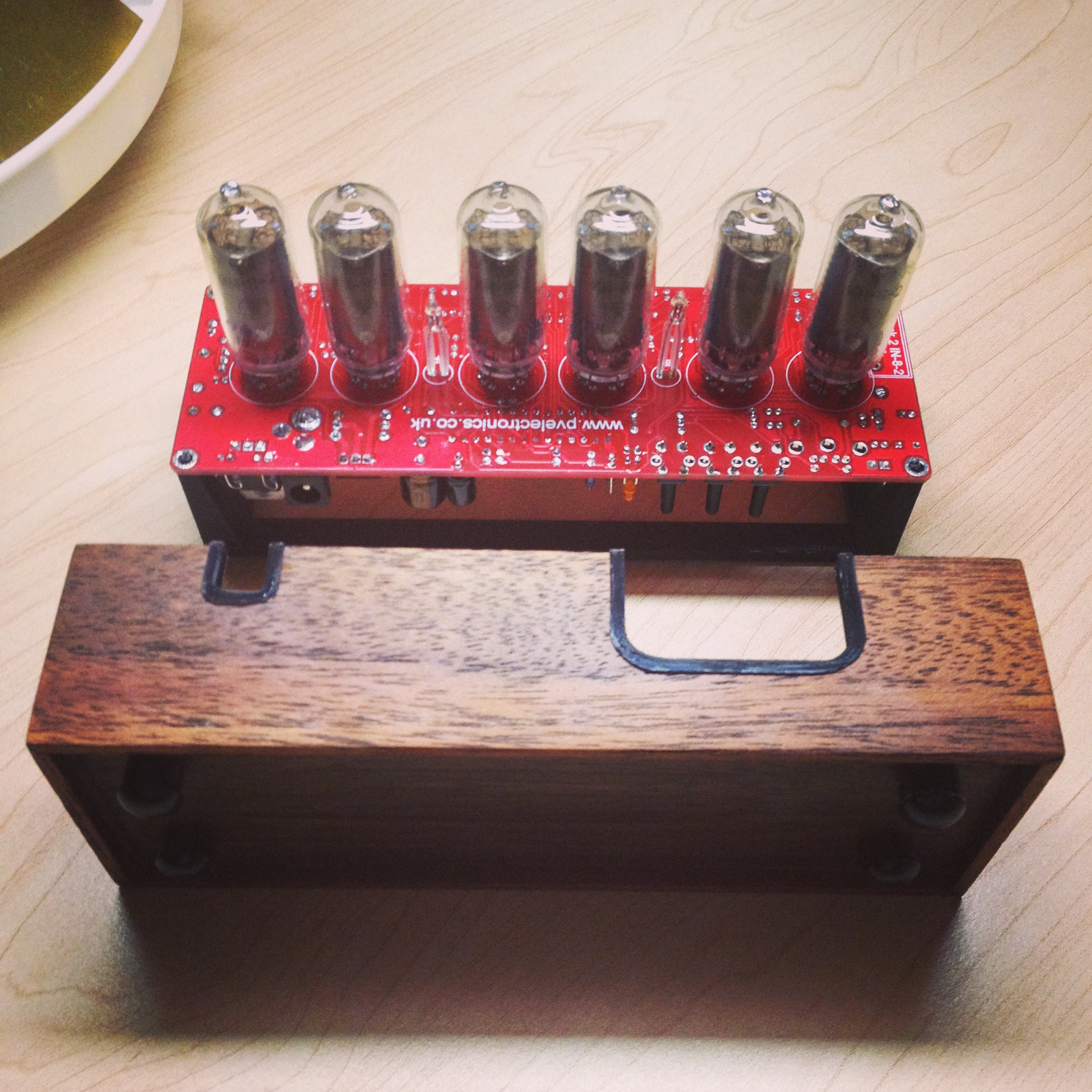
The board was mated to the armature next. I used a torch to set the pegs as rivets. At this point, the approximate form can be seen!
The electronic hardware has a variety of controls and a 12v socket. The case needs to account for the control buttons, alarm light, and socket. I designed and modeled gaskets, printed them in black PLA, and then inscribed their contours on the case itself. Then I cut away the appropriate amount of wood. You can also see the feet in the image below. This is a combination of furniture tacks and 3D printed PLA. The result is a foot peg that will not scratch, is lightweight, and has a desirable shape that matches the style of the rest of the clock.
I’ve mounted the gaskets in the following image. I chose to use epoxy for the assurance that they would have no chance of falling out and potentially damaging the electrical. These gaskets will be interacted with the most (by fingers and plugs).
At this point, once drying has fully completed for the casework and gaskets, the board, armature, and case can all be integrated. For safety, I’ve allowed another 24 hours of dry time.
Finally, I designed a cover to be printed in black PLA. PLA is a great material; it is low heat and can be heat treated to achieve matte or gloss finishes. I’ve used a heated build plate to apply a mirror finish to the cover. This reflects the tubes themselves while not distracting from the overall form. It also creates a visual separation between the wood grain and the display. Ideally, the two are visually balanced when observed in situ.
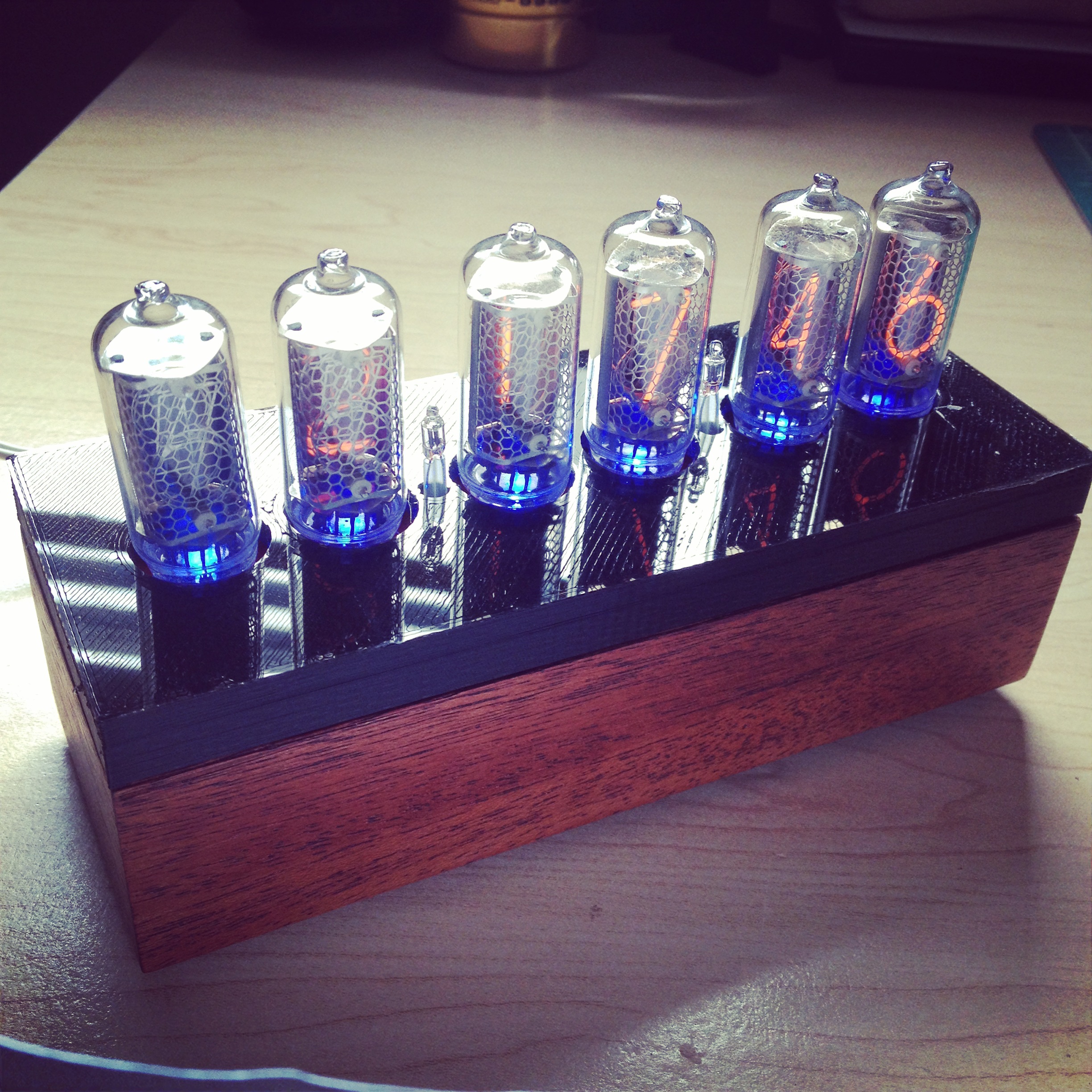
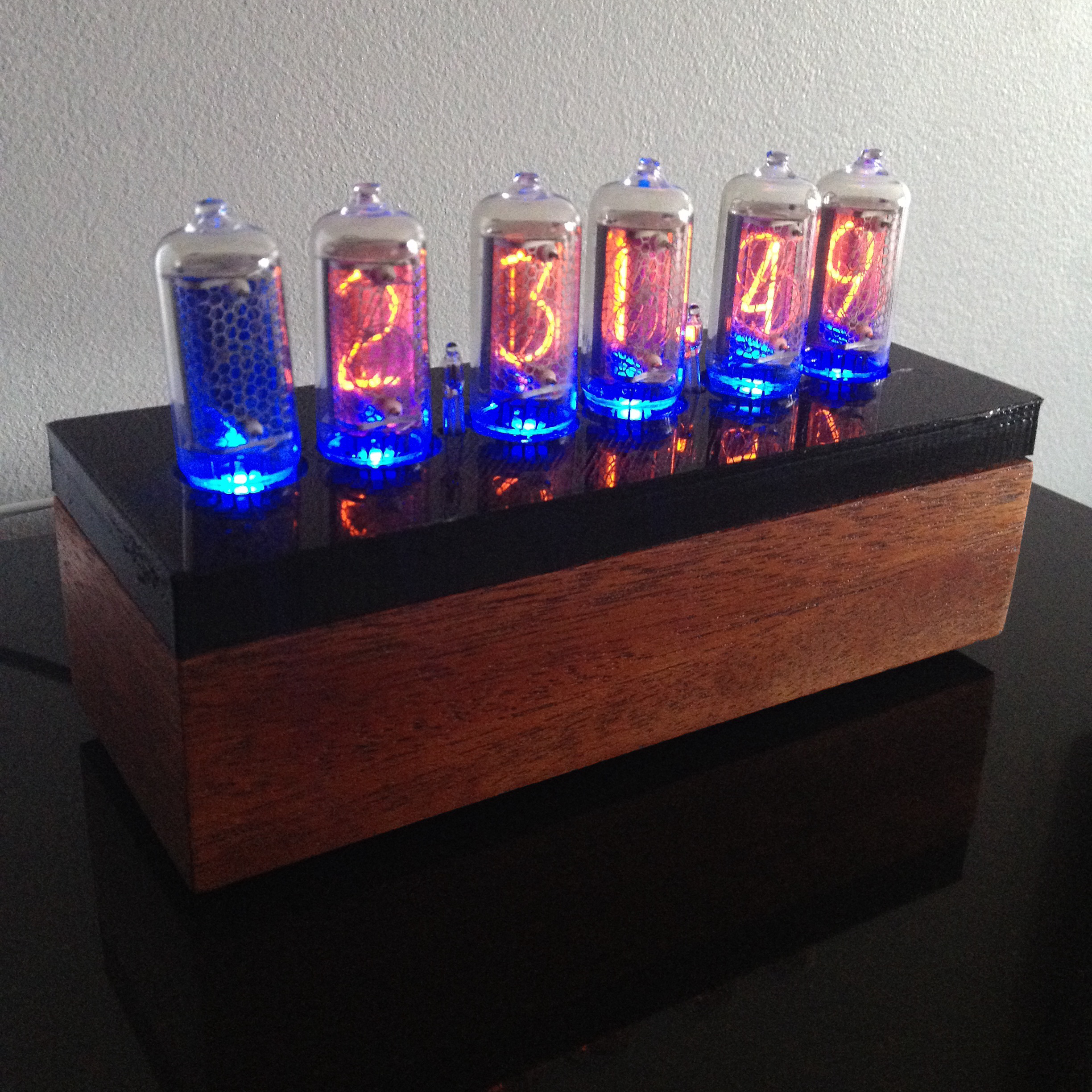
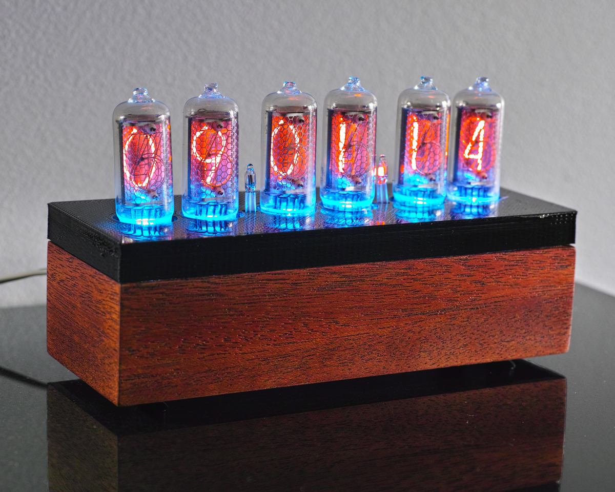
The finished product now sits in situ. It’s quite bright and the LED is a deep blue. In certain bright lighting, the blue shifts toward aqua. It provides a really strong contrast to the orange and I quite like the effect. All said, the complete project took many weeks but only in short bursts of time (other than the initial electrical). In the future, I may replace the 3D printed cover with milled acrylic and apply fresh wax to the case. I’ve put it into a date-time mode where the date is displayed on a regular interval, with the primary display being time. The neon bulbs (small, between the integers) indicate the pulse of the seconds and AM vs PM. The left neon bulb is lit in the morning and the right bulb indicates evening.